A first receiver: forty metres of twisted pair and the Volyn roundtable

I wanted to hear the bands on a set I had first held in my hands in pieces. Not buy something finished and switch it on, but solder it, align it, get a wire six metres up and catch live voices. It happened on 80 metres, on a Sunday morning.
What exactly I was building
“JUNIOR” is a kit by Serhii Belenetskyi, US5MSQ: a beginner's HF receiver for two bands, 80 and 20 metres. A receiver only: there is no transmit path in it at all — an antenna at the input, headphones at the output, and nothing going back on the air. I read his article about building it and bought the kit directly from him.
Choosing a kit rather than my own design from scratch was deliberate. A first receiver has one trap: it stays silent, and it is not clear why. The circuit? The assembly? The components? The antenna? Propagation? A ready kit crosses the circuit and the components off that list. What remains is my soldering and my antenna — exactly what I wanted to learn.
The circuit in one paragraph
A single-conversion superheterodyne. The antenna signal passes through an adjustable attenuator and a two-pole bandpass filter into the first SA612 mixer. The local oscillator is a VFO at 8.5–8.8 MHz for 80 metres or 9–9.35 MHz for 20; a relay switches the bands. The 5 MHz intermediate frequency goes through a four-crystal filter 2.4 kHz wide, is amplified by a single transistor stage, and reaches a second SA612 working here as a product detector with a 4998 kHz carrier oscillator. Then an LM386 and the headphones. Tuning is by varicap from a potentiometer — the knob turns a voltage, not a capacitor.
| Parameter | Value |
|---|---|
| Bands | 3.5–3.81 and 14–14.35 MHz |
| Intermediate frequency | 5 MHz, crystal filter 2.4 kHz at −6 dB |
| Audio bandwidth | 300–2700 Hz |
| Sensitivity | 0.6 µV at 10 dB S/N |
| Image rejection | at least 40 dB |
| AGC range | at least 50 dB |
| Audio output | at least 300 mW into 8 Ω |
| Supply | 9–12 V |
| Board | 89×66 mm |
These are the author's figures from the description, not my measurements. I did not yet know how to make my own.
Three evenings with a soldering iron
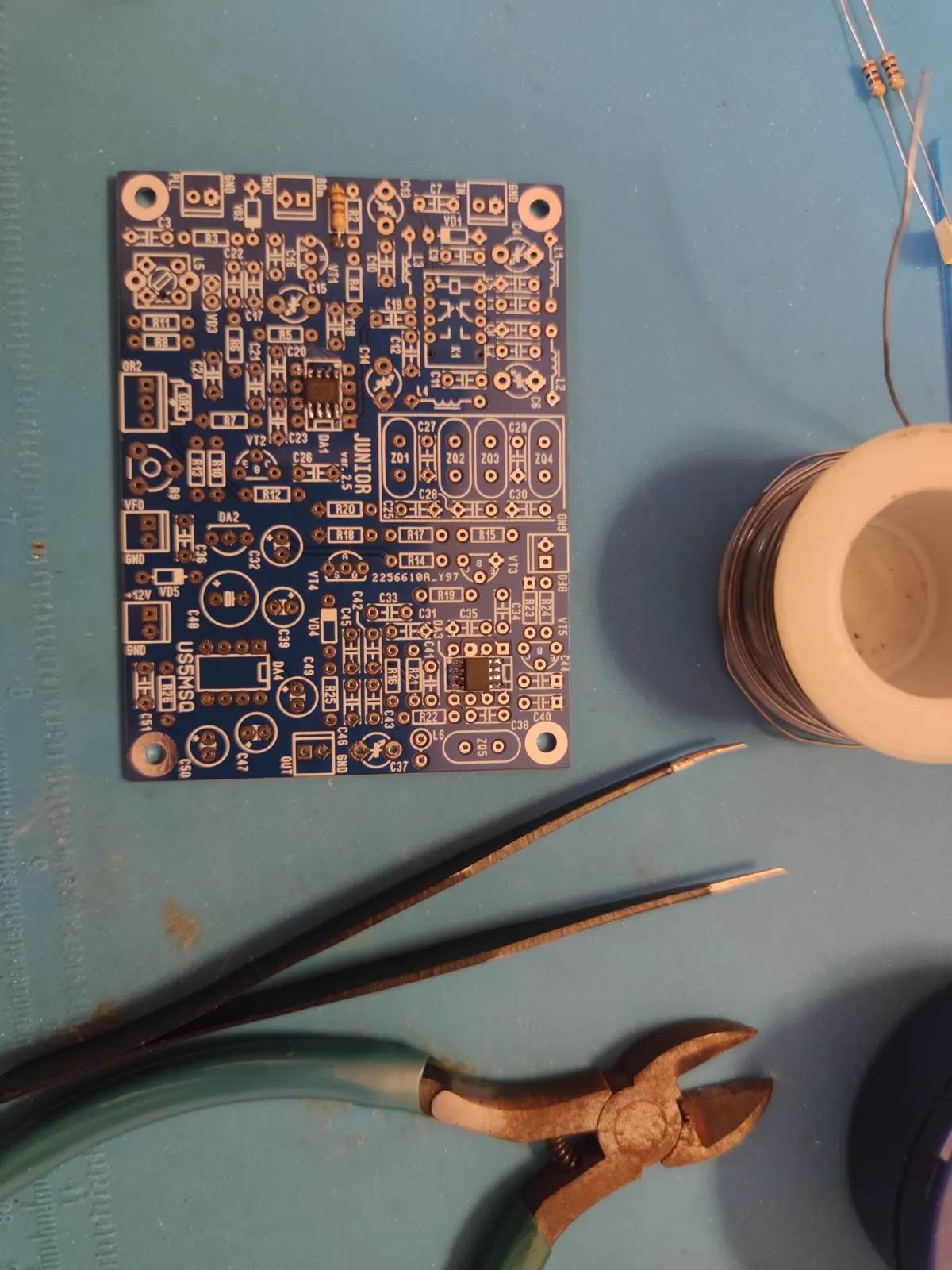
12 November 2023, the bare version 2.5 board. Double-sided glass-epoxy with mask and full silkscreen: every position is labelled, nothing has to be hunted for. Both mixers, in SOIC packages, were already on the board — the author solders the SMD parts himself, and for a beginner's kit that is the right decision: the finest work is already done, and everything left can be soldered with an ordinary tip.
The author's order: resistors and capacitors first, then the chokes L1–L4 standing 1–1.5 mm above the board, L6 vertically, then connectors, the relay, the transistors, and the integrated circuits last.
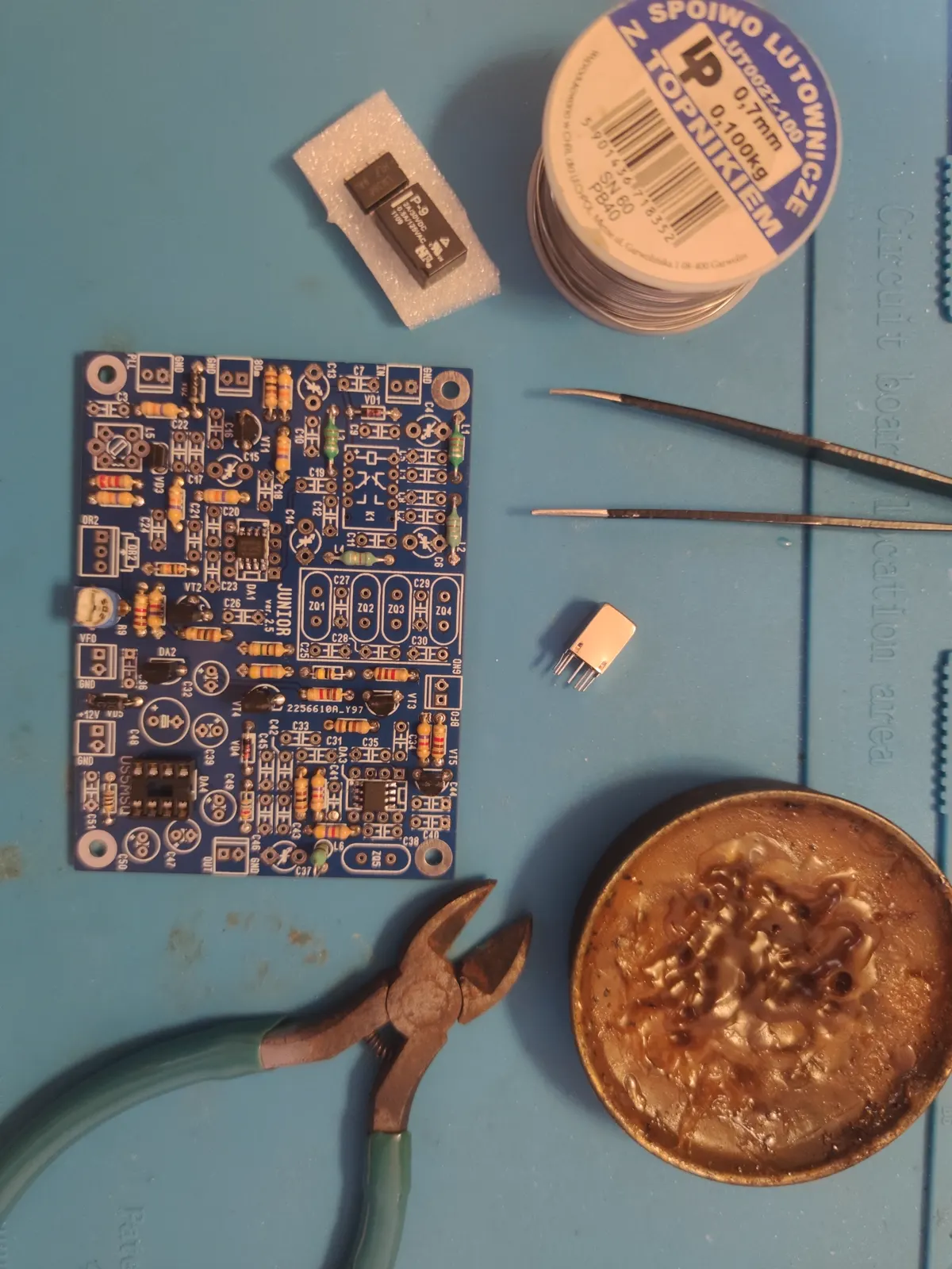
The 1–1.5 mm requirement looks like pedantry one is tempted to ignore. Do not: L1–L4 are not “supply-rail chokes” but the inductors of the input bandpass filter. How high they stand above the solid ground plane goes into the tuned circuit along with them.
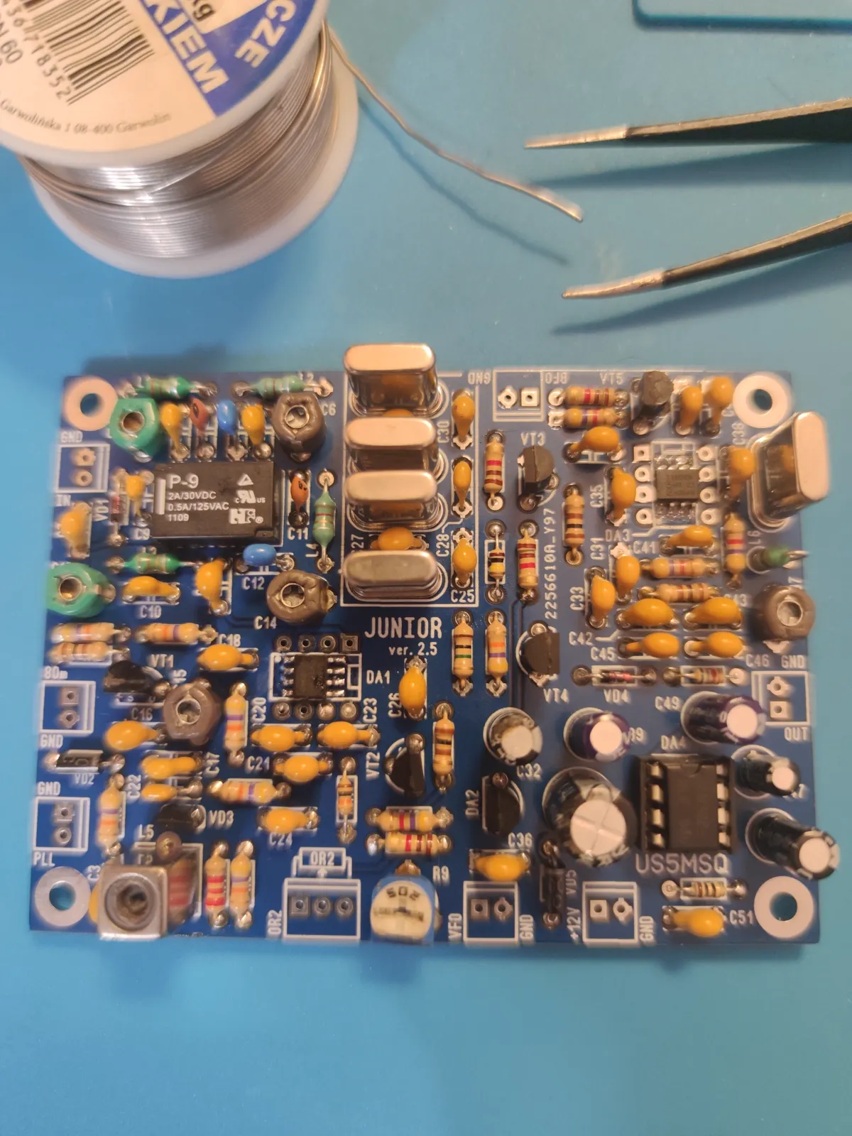
By 14 November the board was assembled. The four filter crystals ZQ1–ZQ4 lie flat in a row down the middle; the fifth, the carrier crystal, sits apart beside coil L6. The only chip in a socket is the LM386, and that too makes sense: if a beginner burns something out, it will be the audio amplifier.
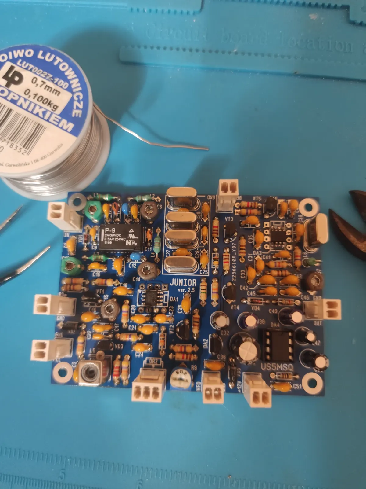
17 November, the connectors. All external wiring goes to screw terminals, with no wire soldered straight into a hole: the board can be lifted out of the case without switching the iron on. At a stage when you do not yet know what will need checking, that saves you.
Alignment: four steps and a screwdriver
Here is where a kit from its designer differs from “built from a magazine article”. The whole procedure is written as a sequence in which each step is verified before the next.
- Operating points. Voltages at the test points, tolerance ±10 %. If one is wrong, you cannot go on, because the remaining steps measure its consequences.
- Carrier frequency. Set trimmer C37 to 4998.00 kHz. This is the adjustment that decides how people sound: the crystal filter stands still, and where the audio zero lands within its passband is set by the carrier oscillator. An error of a couple of hundred hertz does not break reception — it makes voices either nasal or thin.
- Setting the band edges. On 20 metres the top edge with the core of L5 and the bottom with resistor R9; on 80, the bottom edge with trimmer C15.
- Input circuits. On 80 metres, trimmers C6 and C14 for maximum signal around 3650 kHz; on 20, C4 and C13 at 14150 kHz.
No instruments beyond the digital display were needed: it is also the frequency counter.
The case
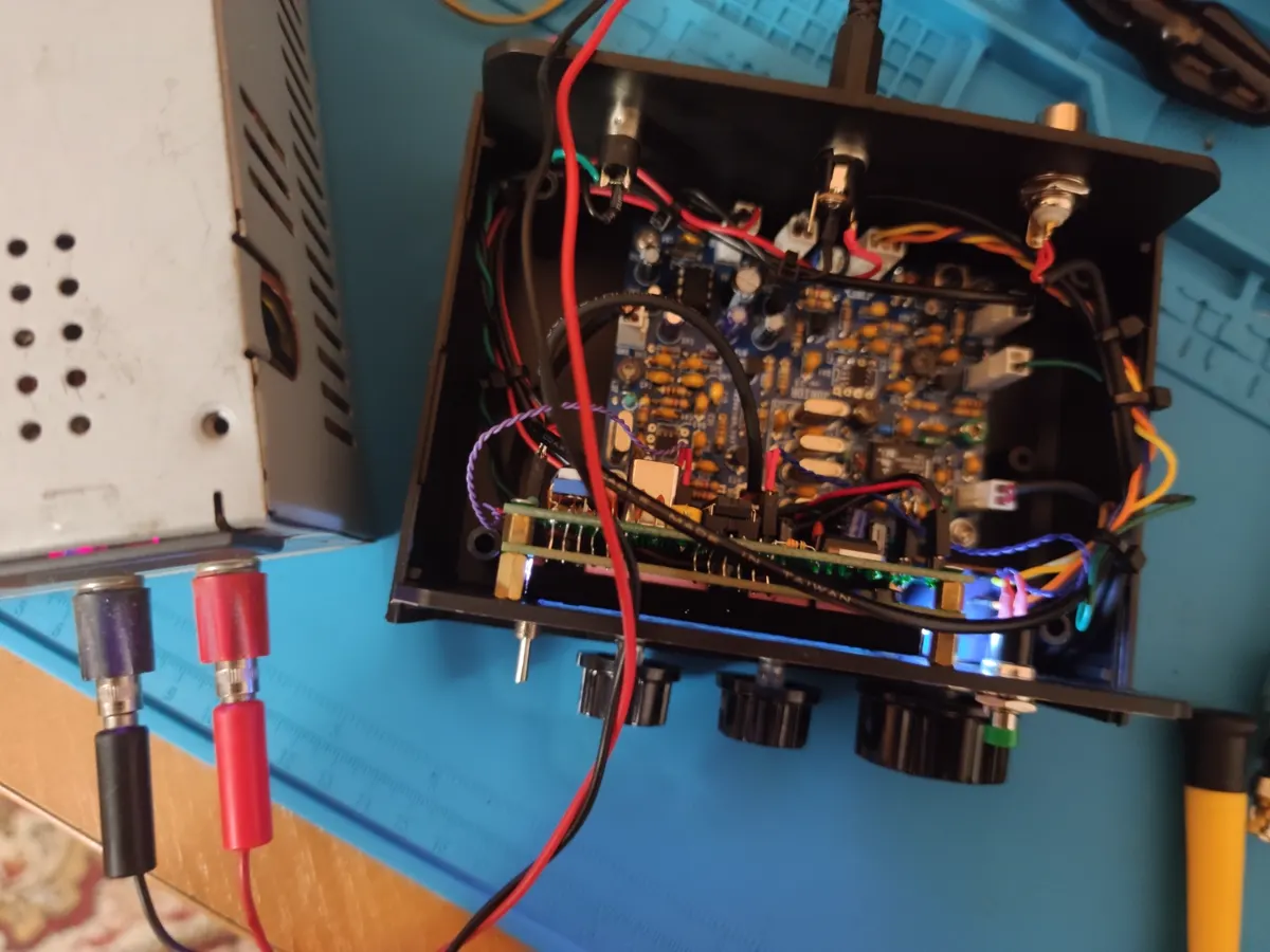
28 November, into the case. The board stands on pillars in the far corner, with the A16-PLL digital display in front of it. The panel holes are marked out from a template supplied with the kit, and a self-adhesive fascia goes over the top. It looks incomparably better than my metalwork deserves — which is exactly why the template is in the kit.
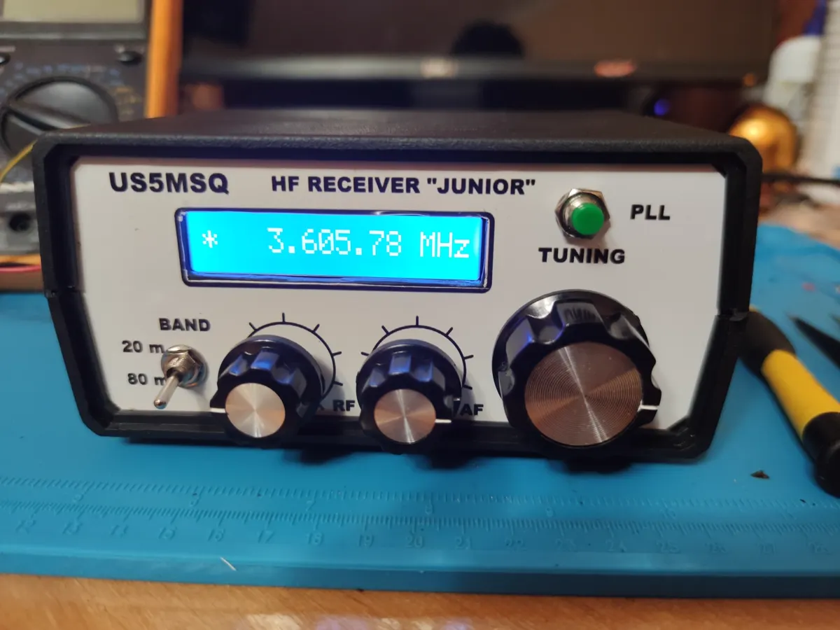
The green PLL TUNING lamp is the display's automatic frequency control. The VFO here runs on a coil and a varicap, and it drifts: for the first few minutes after switch-on the frequency moves noticeably. The display not only shows the frequency but also pulls the oscillator back, and with it the set stays on a station for as long as the station is talking.
What it draws
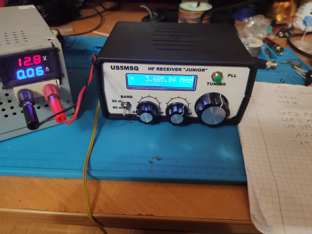
12.8 V, 0.06 A. Sixty milliamps including the display — which fits the specification: the author quotes 30 mA on 80 metres without the display, plus up to 40 mA for the display itself.
The figure matters not in itself. A receiver with that appetite runs a day from a power bank and does not care whether the mains is on.
The antenna: forty metres of twisted pair
The most interesting thing in this story cost less than the connectors on the back panel.
Two legs of twenty metres each, ordinary twisted pair, six metres up. Forty metres of wire in all.
Now let us work out what came of it. At 3.605 MHz a wavelength is 83.2 m and a half wave 41.6 m; with the shortening factor applied, a real resonant dipole comes out at about 39–40 m. So “just the wire that happened to be there” turned out to be almost exactly a half-wave dipole for 80 metres. The resonance happened by itself, with no intention on my part.
Six metres of height is 0.07 of a wavelength. By any textbook that is “low”, and by any textbook that is bad. For what I wanted to hear it is exactly right. An antenna's pattern does not care which way the signal is travelling: a dipole that at this height would radiate almost straight up equally hears mostly from above. And what comes from above on 80 metres is whatever bounced off the ionosphere close to vertically — stations thirty to a hundred kilometres away. That is precisely the distance at which the regional roundtable's members sit.
The angle is easy to work out. In the morning on 3.6 MHz the signal is turned back by a layer two to three hundred kilometres up; for a correspondent a hundred kilometres away that is an arrival angle of about eighty degrees above the horizon, and for one thirty kilometres away, practically vertical. The closest are also audible by ground wave, which on 80 metres reaches a few tens of kilometres, but the rest arrives from exactly there — from above.
And here is where the advice “hang it higher” hides its catch. That advice is about DX, that is, about low angles, and to get them on 80 metres a dipole has to go up half a wavelength — forty metres. At exactly that height a null appears at the zenith, and such an antenna hears a neighbour thirty kilometres away worse than mine at six. All I lost by hanging it low is not direction but efficiency. In English this mode is called NVIS, and my antenna is a textbook case of it, arrived at with no intention whatever.
Ground losses under a wire that low are appreciable. On receive that barely matters: on 80 metres the floor is set not by the receiver but by atmospheric noise, and that arrives through the same antenna. The losses attenuate signal and noise alike — the ratio between them does not change.
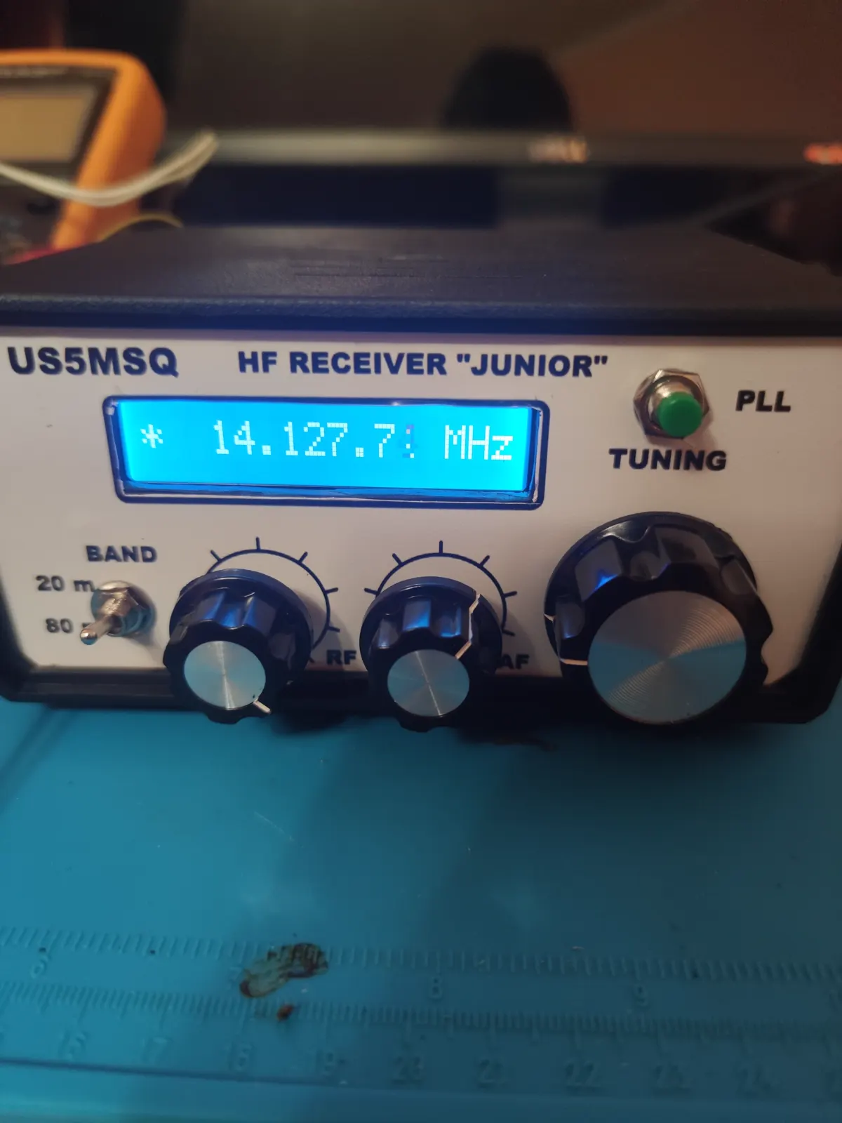
On 20 metres the same wire is 1.9 wavelengths: a multi-lobed antenna, sensitive to low angles. So 14 MHz comes in as well, except that the antenna chooses the directions for itself rather than for me.
The roundtable
The Volyn Radio Amateurs League meets every Sunday at eight in the morning on 3.605 MHz.
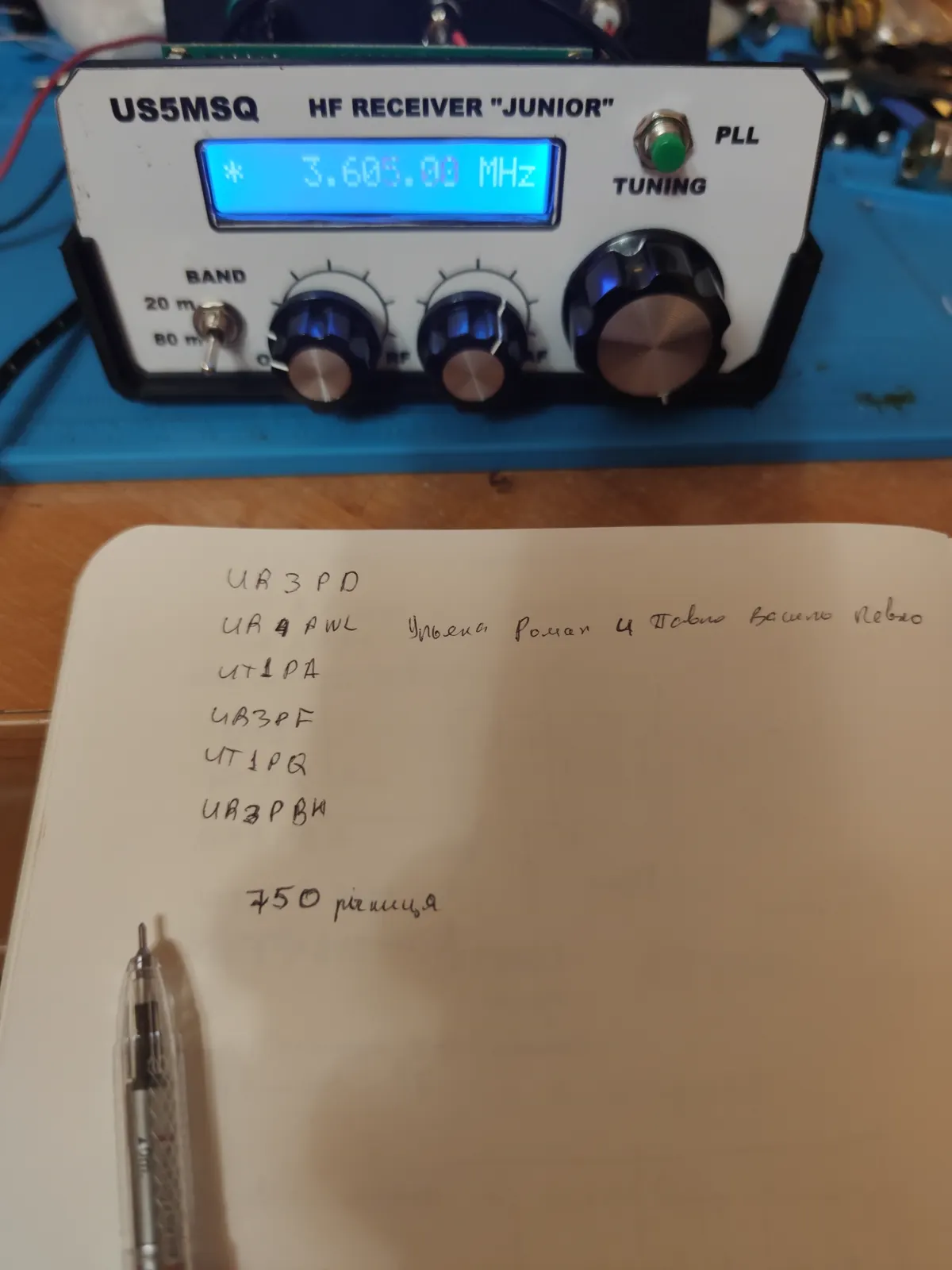
24 December 2023, 8:43, a Sunday. The display reads 3.605.00, and beside it an open notebook in which I wrote down the callsigns as they were spoken: UR3PD, UR4PWL, UT1PA, UR3PF, UT1PQ, UR3PBW. Lower on the same page, a line reading “750th anniversary”: the roundtable does not talk only about equipment.
That was the moment the whole thing was for. Not “the receiver works” — it worked on empty hiss too. But when voices came out of the headphones calling each other by name and arranging the next Sunday, it became clear that the wire outside and the box on the table were connected to something alive.
What I took from it
Selectivity is made of hardware. The 2.4 kHz bandwidth is set by the crystal filter, and it cannot be “adjusted”. Narrow or wide was decided when I laid four crystals in a row.
The carrier frequency decides how people sound. One trimmer, two hundred hertz, and the timbre of the whole band is different. Before JUNIOR I thought sidebands were a matter of theory.
The attenuator is not decoration. In the evening on 80 metres a strong neighbour overloads the front end, and the RF knob is needed not “just in case” but every evening.
Stability is an engineering problem of its own. A VFO on a coil and a varicap drifts, and no quality of soldering fixes it. What fixes it is automatic frequency control — digital laid over analogue.
The antenna is half the receiver. Forty metres of twisted pair six metres up gave more than any amount of trimmer-turning inside the box. That is the cheapest lesson of the lot, and the most important.
What it does not do
To be honest, so that nobody buys the kit with the wrong expectations:
- it does not transmit — it is a receiver, full stop;
- one bandwidth for every occasion: no narrower filter for Morse, and no wider one;
- no S-meter, so a correspondent's strength is judged by ear;
- two bands, 80 and 20, and nothing else.
These are not complaints. They are the boundaries at which the next set begins — and that is exactly why the next one on my bench is a direct-conversion receiver, built from scratch, with no kit and no one else's board.
Sources
- Radio kit: the JUNIOR receiver for the beginning short-wave listener — description, circuit design, assembly order and alignment by the author, US5MSQ.
- Volyn Radio Amateurs League — the frequency, day and time of the regional roundtable.