Helical resonator filter calculator
A helical resonator is a quarter-wave line coiled into a helix and put inside a shield. At VHF and UHF it gives a Q in the hundreds or thousands where an LC circuit gives tens.
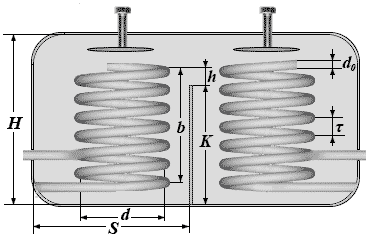
| Operating frequency f₀ (MHz) | |
| −3 dB bandwidth ΔF (MHz) | |
| Permissible passband loss α (dB) | |
| Input impedance Ri (Ω) | |
| Output impedance Ru (Ω) | |
| Helix diameter d (cm) — leave empty for the optimum | |
| Resonator | |
| Unloaded Q, Qu | |
| Loaded filter Q, Ql | |
| Resonator characteristic impedance Z₀ | |
| Calculated passband loss α₀ | |
| Helix | |
| Helix diameter d | |
| Helix length b | |
| Number of turns N | |
| Winding pitch τ | |
| Wire diameter d₀ | |
| Input tap (turns from the cold end) | |
| Output tap (turns from the cold end) | |
| Shield and partition | |
| Shield width S | |
| Shield height H | |
| Window above the partition h | |
| Partition height K | |
📐 Formulas
The design runs from the requirements to the hardware: the passband and the permissible loss give the Q you need, the Q gives the diameter of the helix, and the diameter gives every remaining dimension.
Qu = (f₀/ΔF) · 1.414 / (10^(α/20) − 1)      required Q
d  = Qu / (35.9·√f₀)                         helix diameter, cm

b  = 1.5·d                                   length of the helix
S  = d / 0.66                                width of the shield
H  = 1.6·S                                   height of the shield
N  = 2674 / (f₀·d)                           number of turns
τ  = b / N                                   winding pitch
d₀ = τ / 2                                   wire diameter
Z₀ = 136190 / (f₀·d)                         characteristic impedance of the resonator
f₀ is in megahertz, the lengths are in centimetres.
Tap points. The loaded Q of a two-section filter is Ql = 0.707·f₀/ΔF:
X = π/4 · (1/Ql − 1/Qu)
tap(R) = arcsin( √(0.5·X·R/Z₀) ) · N · 2/π
The wall between the sections:
h = d · (10·α/f₀)^(1/1.91)
K = 1.5·d + 0.3·d/0.66 − h
The reverse pass (with the diameter entered by hand):
Qu = 35.9·d·√f₀
α  = 20·log₁₀( 1 + 1.414·(f₀/ΔF)/Qu )
Notation:
f₀— working frequency [MHz]ΔF— passband at the −3 dB level [MHz]α— permissible in-band loss [dB]Qu— unloaded Q of the resonatord— helix diameter [cm]Z₀— characteristic impedance of the resonator [Ω]
- The proportions (b = 1.5d, S = d/0.66, H = 1.6S) are empirical: depart from them badly and the calculation no longer holds
- If the passband you ask for is narrower than the achievable Q allows, the calculator says so: Ql cannot exceed Qu
- The calculated Q is an optimistic upper bound: the real one depends on the surface finish of the conductor and on the contact between the helix and the shield
🎯 Where it is used
- VHF band-pass filters in receivers and transmitters.
- Preselectors where an LC circuit does not give the selectivity needed.
- Protecting a receiver front end from strong out-of-band signals.
- The ±0.1 cm buttons fit the diameter to the enclosure you have: the calculator runs backwards and shows what the Q and the real loss then become. The price of a smaller box is visible at once.
- Silver-plating the inside of the shield and the helix itself raises the Q noticeably — at VHF that is not cosmetic.
- The taps are counted from the «cold», earthed end of the helix. Mixing up the ends is the commonest mistake when tuning.
© 2026 UR3PKI · CyberDev.Space · Content licensed under CC BY-NC-SA 4.0.
How to cite this calculator
UR3PKI. «Helical resonator filter calculator». CyberDev.Space. https://cyberdev.space/en/radio/calculators/coils/helical_resonator (licence CC BY-NC-SA 4.0).The licence lets you use this material freely, including in teaching materials, but only with attribution to the author and a link to the source.