E-core ferrite coil calculator
When you need this
EE, EI and EC cores are the backbone of home-made transformers and chokes for switching gear. This method is for the case where AL is unknown but the dimensions and the permeability are not.

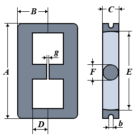
| Core type | |
| Required inductance L (µH) | |
| Dimension A — overall height (mm) | |
| Dimension B — overall depth of one half (mm) | |
| Dimension C — core thickness (mm) | |
| Dimension D — centre leg length (mm) | |
| Dimension E — window height (mm) | |
| Dimension F — centre leg width (mm) | |
| Cut-out size b — EC only (mm) | |
| Gap in the centre leg g (mm) | |
| Ferrite permeability μr | |
| Result | |
| Number of turns N | |
| Inductance you will get | |
| Effective magnetic path length le | |
| Effective cross-section Ae | |
| Effective volume Ve | |
| Effective permeability μe | |
| Inductance factor AL | |
| Peak current limited by saturation | |
📐 Formulas
The IEC 60205 standard: a complicated core is replaced by an equivalent toroid that, with the same number of turns, has the same electrical parameters. The magnetic circuit is split into five sections.
Primary parameters from the catalogue dimensions:
h = B − D      yoke thickness
q = C          core depth
s = F / 2      half-width of the centre limb
p = (A − E)/2  thickness of the outer limb
Section lengths:
l1 = l3 = 2D   for EE and EC
l1 = l3 = D    for EI — one half of the core is flat, so the path is half as long
l2 = E − F
l4 = π·(p + h)/4
l5 = π·(k·s + h)/4,   k = 1 for a rectangular limb, 1.1918 for a round one
Cross-sections:
A1 = 2·q·p − π·b²/2      yoke; for EC the cut-out is subtracted
A2 = 2·q·h               outer limbs
A3 = π·s²  or   2·s·q    centre limb, round or rectangular
A4 = (A1 + A2)/2         A5 = (A2 + A3)/2
Effective parameters and inductance:
C1 = Σ lᵢ/Aᵢ        C2 = Σ lᵢ/Aᵢ²
le = C1²/C2         Ae = C1/C2         Ve = C1³/C2²

μe = μr / (1 + g·μr/le)                effective permeability with the gap
L [µH] = 1000 · μ₀ · μe · N² / C1
Ip = B · N · Ae / L,   B = 0.3 T
Notation:
A…F— catalogue dimensions of the core [mm]b— size of the cut-out in the limb, EC only [mm]g— gap in the centre limb [mm]le— effective magnetic path length [mm]Ae— effective cross-section [mm²]μe— effective permeability
Limits of the calculator:
- The method is accurate to about ±30 %. The main reason is how tightly the two halves of the core meet: even a 0.01 mm gap at the joint lowers μe noticeably
- If the datasheet gives AL, use it. This method is for when AL is unknown
- Core losses under alternating current are not included — and it is those that decide how hot it runs
- The peak current is worked out for a flux density of 0.3 T: for powdered cores it is at least three times higher
🎯 Where it is used
- Chokes and transformers in switching power supplies.
- Energy-storage chokes in gapped converters.
- Estimating the saturation current before you start winding.
Practical notes:
- Note how a 0.5 mm gap drops the permeability from 2200 to a few tens. It is the gap, not the material, that sets the inductance of a gapped core — and that is a good thing, because the gap also stabilises it.
- The number of turns is rounded up: the inductance must not come out below the figure you asked for.
- For EI the magnetic path is half as long as for an EE of the same size — one half of the core is flat.
© 2026 UR3PKI · CyberDev.Space · Content licensed under CC BY-NC-SA 4.0.
How to cite this calculator
UR3PKI. «E-core ferrite coil calculator». CyberDev.Space. https://cyberdev.space/en/radio/calculators/coils/e_core (licence CC BY-NC-SA 4.0).The licence lets you use this material freely, including in teaching materials, but only with attribution to the author and a link to the source.