Ferrite rod coil calculator
A receiver's loopstick antenna, or a choke on a ferrite rod. The model accounts not only for the permeability of the ferrite but also for the length of the winding and its offset from the middle of the rod.
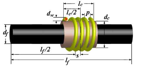
| Required inductance L (µH) | |
| Ferrite rod | |
| Rod length lf (mm) | |
| Rod diameter df (mm) | |
| Initial ferrite permeability μr | |
| Coil | |
| Former diameter dc (mm) | |
| Offset of the coil centre from the rod centre s (mm) | |
| Wire diameter dw (mm) | |
| Winding pitch p (mm) | |
| Estimate the pitch automatically | |
| Result | |
| Number of turns N | |
| Gain from the rod, Lf/Lair | |
| Winding length lc | |
📐 Formulas
A rod is an open magnetic circuit: the flux closes through the air, so the real gain is set by the geometry, not by the permeability of the material. For a rod with μi = 600 the gain comes out at 40…70 — an order of magnitude less.
Step 1. The inductance of the coil «in air» — Lundin's formula minus Rosa's correction, plus a correction for a spaced winding:
ΔL_pitch = −10⁻⁴ · Dk · (p/dw − 1) · (12 − p/dw)/4 · N for N greater than 4
Step 2. The gain from the rod:
free    = lf − lc
stray   = 5·10⁻⁴·π·free / (ln(2(lf+df)/df) − 1)
damping = 1 / (1 + (free/df)^1.4 / (5·μr))
n       = (damping·stray + 0.002·df) / (0.002·dc)

reach   = lc + 0.45·dc
r       = (reach/dc) · 5.1 / (1 + (dc/reach)·2.8)
μfe     = (μr − 1)·(df/dc)² + 1

Lf/Lair = (1 + r) / (1/n + r/μfe)
Step 3. The correction for the offset of the coil from the centre, x = 2s/lf:
kx = 0.995 + 0.3013663x − 7.6027344x² + 71.6178135x³ − 363.8218957x⁴
     + 1021.078226x⁵ − 1604.5491034x⁶ + 1318.707293x⁷ − 440.9943706x⁸
Together: L = L_air · (Lf/Lair) · kx
Notation:
L— inductance [µH]lf— rod length [mm]df— rod diameter [mm]μr— initial permeability of the ferritedc— diameter of the coil former [mm]s— offset of the coil from the centre of the rod [mm]lc— winding length [mm]
- The winding pitch must lie between dw and 2·dw
- The former diameter between df and 2·df
- The winding shorter than 3/4 of the rod
- The end of the coil no closer to the end of the rod than 1/8 of its length
- This is the most empirical model in the section: expect errors of tens of per cent, especially on short rods
🎯 Where it is used
- Loopstick antennas for long-, medium- and short-wave receivers.
- Chokes on ferrite rods.
- Estimating the effective permeability of a particular rod.
- The «offset» field is not a formality: sliding the coil along the rod is exactly how a loopstick is trimmed to the inductance you want.
- The more of the rod the winding covers, the lower the gain: a short free end closes the flux less well.
- The model makes sense for permeabilities above roughly 100. For low-permeability rods the result will be far too optimistic.
© 2026 UR3PKI · CyberDev.Space · Content licensed under CC BY-NC-SA 4.0.
How to cite this calculator
UR3PKI. «Ferrite rod coil calculator». CyberDev.Space. https://cyberdev.space/en/radio/calculators/coils/ferrite_rod (licence CC BY-NC-SA 4.0).The licence lets you use this material freely, including in teaching materials, but only with attribution to the author and a link to the source.