Multilayer inductor calculator
When a single layer is no longer enough: chokes, loudspeaker crossover coils, high-inductance windings on a short former.
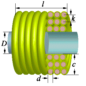
| Required inductance L (µH) | |
| Former diameter D (mm) | |
| Winding length l (mm) | |
| Wire diameter over copper d (mm) | |
| Wire diameter over insulation k (mm) | |
| Estimate the diameter over insulation automatically | |
| Result | |
| Number of turns N | |
| Number of layers n | |
| Winding thickness c | |
| Wire length Lw | |
| DC resistance of the winding | |
📐 Formulas
The coil is not worked out from a single empirical formula — it is literally wound in memory, turn by turn. Each turn is a circular loop with a known radius and position:
turns per layer: Nl = floor(l / k)
layer number:    layer = floor((n − 1) / Nl)
turn radius:     r = (D + k)/2 + k·layer
position:        z = k · ((n − 1) mod Nl)
The inductance is the sum of the self-inductances of the turns plus twice the mutual inductance of every pair:
L = Σ Lself(i) + 2·Σ M(i, j), i less than j
The mutual inductance of two coaxial turns (Maxwell):
k = 2·√(r₁r₂) / √((r₁+r₂)² + (s − g)²)
M [µH] = −0.004π·√(r₁r₂) · [ (k − 2/k)·K(k) + (2/k)·E(k) ]
where K and E are the complete elliptic integrals and g is the geometric mean distance of the wire cross-section, g = e^(−1/4)·d/2.
Derived quantities:
winding thickness: c = n·k
wire length:       Lw = Σ 2πr
resistance:        R = ρ·Lw/S,  ρ(copper) = 0.0175 Ω·mm²/m
Notation:
L— inductance [µH]D— former diameter [mm]l— winding length [mm]d— wire diameter over copper [mm]k— diameter over the insulation, i.e. the pitch [mm]n— number of layers,c— winding thickness [mm]
- The winding is assumed close-wound, turn against turn and row against row: a random («jumble») winding will give a different result
- Interlayer insulation and sectioning are not taken into account
- The former is non-magnetic, there is no core and no shield
- A realistic error for a neat winding is about ±5 %
🎯 Where it is used
- Chokes in supply filters and decoupling.
- Crossover coils in loudspeaker systems.
- High-inductance windings where the former length is limited.
- The computation is quadratic in the number of turns: for coils of a few thousand turns the page will think for a second or two.
- The resistance shown is the DC value. At the working frequency the skin effect and proximity effect make it noticeably higher — which is exactly why multilayer coils have a low Q.
- If the coil comes out too «fat», try a longer former: for the same inductance, fewer layers mean lower resistance and lower self-capacitance.
© 2026 UR3PKI · CyberDev.Space · Content licensed under CC BY-NC-SA 4.0.
How to cite this calculator
UR3PKI. «Multilayer inductor calculator». CyberDev.Space. https://cyberdev.space/en/radio/calculators/coils/multi_layer (licence CC BY-NC-SA 4.0).The licence lets you use this material freely, including in teaching materials, but only with attribution to the author and a link to the source.