PCB coil calculator
When you need this
When the inductor has to be etched on the board: proximity sensors, matching networks, chokes in compact assemblies, wireless power coils.
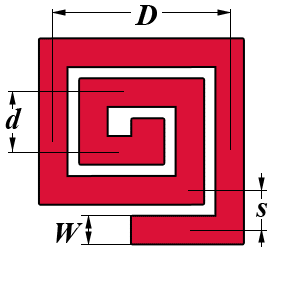
| Turn shape | |
| Required inductance L (µH) | |
| Spiral outer diameter D (mm) | |
| Spiral inner diameter d (mm) | |
| What fraction of the pitch the trace takes, W/s (0…1) | |
| Result | |
| Number of turns N | |
| Winding pitch s | |
| Trace width W | |
| Gap between traces g | |
📐 Formulas
The current-sheet approximation (Mohan, Hershenson, Boyd, Lee, 1999) — the standard formula for planar spiral inductors.
d_avg = (D + d) / 2                 mean diameter
ρ     = (D − d) / (D + d)           fill ratio

L = c₁ · μ₀ · N² · d_avg / 2 · [ ln(c₂/ρ) + c₃·ρ + c₄·ρ² ]
Coefficients by turn shape:
| Shape | c₁ | c₂ | c₃ | c₄ |
|---|---|---|---|---|
| square | 1.27 | 2.07 | 0.18 | 0.13 |
| circular | 1.00 | 2.46 | 0.00 | 0.20 |
Both diameters are given, so the mean diameter and the fill ratio are constants and the dependence on the number of turns is exactly quadratic. The turns are therefore found without iteration:
N = √( L / L(N = 1) )
s = (D − d) / (2N)
W = (W/s) · s
Notation:
L— inductance [µH]D— outer diameter of the spiral [mm]d— inner diameter of the spiral [mm]N— number of turnss— winding pitch [mm]W— track width [mm]
Limits of the calculator:
- The formula was derived for dense spirals: a fill ratio ρ of roughly 0.1…0.9 and W/s no less than 0.3
- Copper thickness and substrate permittivity are not part of the model — they barely affect the inductance, but they affect the self-capacitance and Q a great deal
- The return conductor (the via and the track to the centre of the spiral) is not taken into account
- The formula is accurate to about 3 %
🎯 Where it is used
- Proximity detectors and inductive sensors.
- Matching networks on the board, where a discrete coil does not fit.
- Wireless power transfer coils at low power.
Practical notes:
- The number of turns comes out fractional: a real spiral always ends part-way through a turn. Round down and trim the outer diameter.
- Track width sets the Q and the current rating, but hardly affects the inductance. Take W/s of about 0.5 as a compromise.
- For the same overall size a round spiral gives less inductance than a square one, but a higher Q — fewer corners, fewer losses.
© 2026 UR3PKI · CyberDev.Space · Content licensed under CC BY-NC-SA 4.0.
How to cite this calculator
UR3PKI. «PCB coil calculator». CyberDev.Space. https://cyberdev.space/en/radio/calculators/coils/pcb_spiral (licence CC BY-NC-SA 4.0).The licence lets you use this material freely, including in teaching materials, but only with attribution to the author and a link to the source.